


- Products
- Shock Absorber
-
Shock Absorber
- Products
- Shock Absorber
Shock Absorber
Overview
KOBA’s shock absorbers are hydraulic impact absorption devices designed to absorb impact energy generated in industrial machinery and automation equipment. They protect equipment and provide stable deceleration during operation.
When moving parts of equipment come to a stop, the kinetic energy generated is converted into thermal energy through hydraulic resistance, allowing smooth deceleration. This process effectively reduces the impact and vibration transmitted to machinery and structural components.
As a result, KOBA shock absorbers help extend the service life of equipment while enabling high-speed operation and stable system performance.
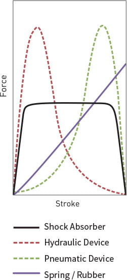
- KOBA shock absorbers provide uniform damping force throughout the entire stroke through their internal orifice structure. This ensures smooth stopping of moving objects while minimizing secondary impact.
- Adjustable models allow users to fine-tune the damping force using an adjustment dial according to impact speed and operating conditions, enabling flexible application across various industrial equipment.
- The integrated housing structure enhances strength and durability, ensuring stable performance even in environments with repetitive impact loads.
- The design can be adapted according to specific installation conditions, allowing flexible application across a wide range of industrial machinery.
- High wear-resistant piston rods and high-quality seals are applied to ensure stable performance and long service life even under demanding operating conditions.
Stable Deceleration Performance
Adjustable Damping Force
Robust Structural Design
Flexible Installation for Various Environments
High Durability and Long Service Life


Shock Absorber’s Overview Structure and Function
- Shock Absorber consists of body, bumper head, piston rod, adjustment dial, and lock nut.
- Thanks to full threaded body it is easy to be installed and precise location fixing is possible.
And surface area is increased to dissipate thermal energy fast to atmosphere. - Bumper head has a role of stopper.
- Piston rod transfers the Impact energy of bumper head to piston.
- Adjustment dial is useful that damping force can be adjusted to impact weight and velocity according to damping conditions.
- Lock nut is useful for installing and fixing shock absorber tightly with body tread installation.

Shock Absorber’s Inner view Structure and Working principle
Inside of shock absorber consists of piston, check valve, accumulator, Inner tube, multiple orifice, return spring, oil, etc. On impacting, the piston rod is inserted into Inner tube and check valve is closed. And it forces oil in the chamber to flow through orifices. At the same time, damping force is generated into piston. Compressed oil which flowed into accumulator is compensating same volume of piston inside. Return process is made by return spring and check valve is opened then piston rod is returned to its original position.

Principal of Energy Absorption
After impacting, compressed oil by piston is to be forced out of Inner tube through orifices. The impact energy is changed into thermal energy then dissipated to atmosphere through threaded body.
Orifice Feature
- Single Orifice
- Single Orifice Type has a dashpot structure with gap between piston and Inner tube or one hole.
resistance characteristic is shown as below. Orifice area is same on entire stroke section, so resistance force is increased immediately after collision. And as stroke progress, the speed decreases and resistance force minimized at the end.

- Multiple Orifices
-
Adjustable
By using multiple orifices, total oil route dimension is decreasing when the stroke is on-going. It enables to maintain total shock absorption safely and softly. Adjustment dial can provide best deceleration features against various collision cases.

-
Self compensating
Operation principal is same of adjustable type. When it set to the optimized orifices’ area is applied, adjustment is not possible after that. Diagram A1 shows high velocity – light impact mass, B1 shows low velocity-heavy impact mass.
